
1. Synthesis setup-methane diffusion flame
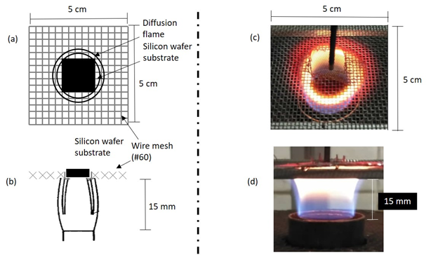
The CNT synthesis setup employed a laminar methane diffusion flame burner as shown in Figure 1 with a concentric fuel and oxidizer outlet tube with a 17 mm and 26 mm diameter, respectively. The positioning system is installed for the sampling method, where the catalyst substrates or nickel wire were inserted horizontally into the flame at desired location and various heights above burner (HAB) with high accuracy and repeatability. The entire synthesis was done at atmospheric pressure within a burner enclosure equipped with an extractor fan to minimize the surrounding air’s entrainment and maintain continuous gas flow. The methane gas of 99.995% purity flows out of the central tube, controlled by Omron flow sensor at a fixed rate of 0.3 slpm. The oxidizer consists of a mixture of oxygen 99.9% and nitrogen 99.9% purity, controlled by a precision metering valve with HoneywellTM sensors, flows out of the concentric tube at a various flow rates as needed. The samples were exposed in the flame at various duration as well.
2. Flame characterization
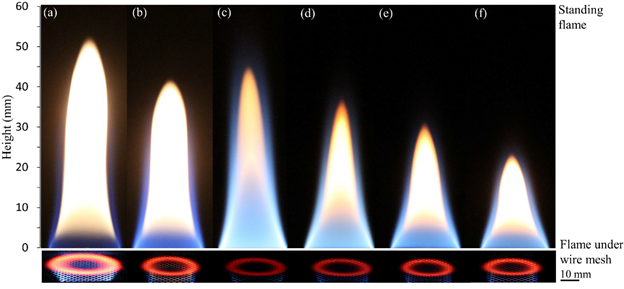
Effects of parameter changes is also studied towards the characteristics of the standing flame and its effects towards CNT growth.
3. Wire-based Macro-Image Analysis (WMA) and growth on nickel wire
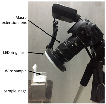
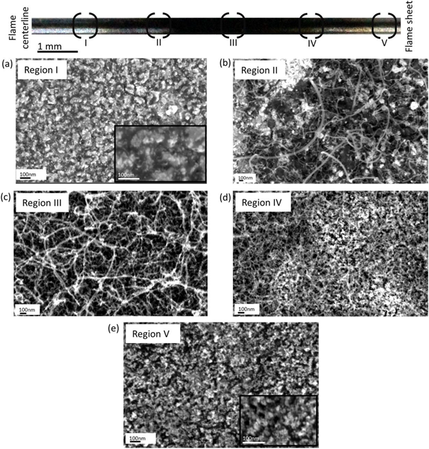
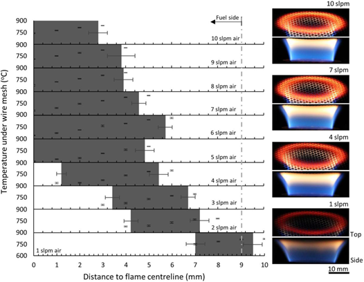
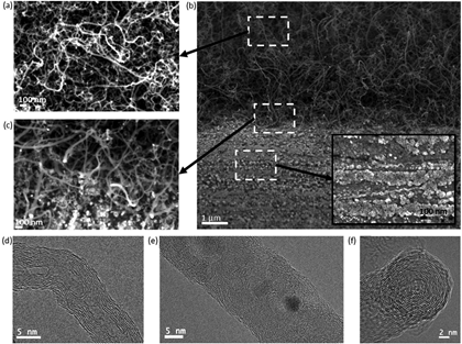
The present study provides a detailed sensitivity and accuracy evaluation of a simple wire-based macro-image analysis (WMA) method for the measurement of steady-state and temporal change of growth region size for multiwalled carbon nanotubes (MWCNT) in a methane diffusion flame with varied air flow rate at atmospheric condition. The WMA method was developed to simplify the MWCNT deposit region identification using the image produced by digital single-lens reflex (DSLR) camera and post-processed using baseline data that was gathered through a one-time SEM analysis. Pure nickel wire was positioned in the flame with a stainless-steel wire grid placed on top of the substrate wire to redistribute the flow field. The MWCNT deposit region that is confined in the fuel-rich region at the inner side of the flame sheet shifts toward the flame centerline with the increase of the air flow rate from 1 to 10 slpm due to the shift of the flame sheet in the same direction. The inception and growth of MWCNT are consistently observed together with the formation of amorphous carbon layer, which has been verified based on detailed SEM analysis. WMA method is proven to be a simple yet reliable measurement of CNT deposit region with minimal use of SEM images processing, which is especially practical for the growth region analysis in a large environment of heterogeneous synthesis.
4. Growth of CNT on silicon substrate

CNT has been successfully grown on silicon substrate via catalyst impregnation (titration) method. The formation of nanoparticles and growth of CNT is observed and analyzed. Physically, the black spots on the substrate indicate the area where possible CNT has grown.
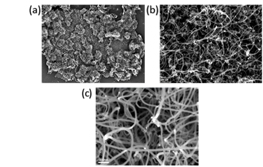
FESEM images confirmed the formation of tubular, straight, and long CNT strands with average diameter of 38nm.
